An incomplete, helpful guide to not burning down your business.
Low Voltage Wiring
(Part 1 should be read first)
This is what you should be using. Low voltage wiring by definition is less than 49V. For our purposes, we’ll be dealing mostly with 24V, 12V, or 5V. Using a lower voltage has several advantages, but the most important here is that it’s safer. A simple touch of an AC circuit is enough to burn you, make you jump, or kill you. Low voltage is much more forgiving. You can touch 24V with dry fingers all day and not notice it. DC circuits are usually isolated too, so no path to Earth to shock you either. There is much less ‘force’ behind the electricity (analogy works for this case). Therefore, when someone takes apart your prop, breaks the glass, etc., you are not exposing them to a lethal situation. That is not to say you can’t die from DC, you can. Anything that reduces resistance like a cut or moisture can make DC deadly quickly. Which is another reason to keep current limited in your circuits.
What we are officially trying to do here is fall under Class 2 wiring in the NEC (National Electric Code). If you can do all your work in Class 2, that greatly reduces the fire initiation capability and shocking hazard. This level of protection is provided by the power supply you are using to drop your AC voltage to DC. If it’s a Class 2 supply, then it is limiting the power for you and making your circuits safer. Electrically, Class 2 for us means 100VA (or 100 Watts to keep it simple) at 24V and 60W or 5A Max for 12V and 4.1A max for 24V. Look at the chart below for wire size guidelines and limits.
| Voltage | Current | Power Limit | <=2 Feet AWG | 10 Feet |
| 12V | 5A (max) | 60W | 24 AWG (2.1%) | 14 AWG (2.1%) |
| 12V | 1A | – | 24 AWG (.8%) | 20 AWG (1.7%) |
| 24V | 4.1A (max) | 100W | 24 AWG (1.8%) | 16 AWG (1.4%) |
| 24V | 1A | – | 24 AWG (.4%) | 22 AWG (1.3%) |
How to use this chart: Once you have determined your system voltage, the first line shows the maximum current and power that circuit can provide. Then choose the wire gauge (AWG) according to how long your run is. The number in parenthesis is the percent voltage loss, for a 12V system, each 1% is .12V. For a 24V system, each 1% is .24V loss.
Most cabinet wiring can be done with 24 AWG because of the short runs, but I personally am a fan of 24VDC and will do my wiring with 22 AWG all around because most items in an escape room don’t exceed 1A. If I have a long run (10ft), I will either run 20 AWG or double up the 4 conductor wire into 2 conductors (yes, that works). If you are a 12V fan, I’d run everything in 20AWG. If you are exceeding 1A, then increase gauge accordingly.
You can calculate your own wire gauge requirements here: https://bulkwire.com/help/recommended-wire-gauge-calculator or play with more details here: http://www.calculator.net/voltage-drop-calculator.html. Try to keep your losses below 2%. Read the directions carefully as the conductor length is twice your cable length (there and back).
So which voltage should you use? 12V or 24V are the most common industrial voltages. 24V is the most versatile and it does have the ability to supply more power when required and losses are less. Also, wire gauges can be smaller (read cheaper, less copper) when using 24V. 12V is fine for smaller rooms or if you have some props that only work on 12V (like LED strips). If you know what you are doing, you can mix as required. 5V should NOT be used outside of a circuit board. It is not an industrial control voltage. It is a common power supply for electronics, but best practice is to keep all 5V signals inside the electronics board (or immediate wiring area) and use 12V or 24V for external, longer wires, like power and switches.
This means don’t run your 5V Arduino/Raspberry Pi/other hobby board I/O pins to the outside world. They are too fragile and too sensitive. More on this later.
Basic wiring
Many of the same rules that applied to AC wiring apply to DC wiring. They are just good practice all around.
- Restrict, tether, mount, strap, etc. your wiring. Keeping wiring from getting yanked out of their termination point increases safety a lot.
- Use proper boxes. Don’t leave a connection in midair with wire nuts on it.
- In a box with mixed voltages (AC and DC), keep the AC as far from the DC as possible. You should be able to draw a virtual line down the path where they are kept separate. Generally, components that handle both AC and DC have an isolation rating of 1000V. If it doesn’t, don’t use it.
The key thing to ensure is that there is not any conductive or electrical connection between the primary (high voltage) and secondary (low, safer voltage). Even if a person is connected to ground, because of the lack of connection between the primary and secondary, they won’t get shocked by the high voltage. The 1000V rating basically means the lack of connection is guaranteed up to 1000V, which is a large safety number for 110/220V. - Use approved, high quality power supplies. UL/ETL labels on power supplies are a good indication you are using a quality product. We also recommend using only name brand power supplies, like CUI or Mean Well, as the extra cost is well worth the investment to avoid flaky behavior or failures during a game.
- Keep wiring gauge consistent. If your power supply is limited to 1A, ensure your wire is rated for 1A all around. (This is pretty easy for 1A, but higher currents are more significant.) We don’t recommend you use anything less than 24AWG ever unless you are trying to hide wire.
Power Distribution
Beyond wiring, the main way escape rooms (and most fixed devices) get power is through an AC adapter. These come in a variety of forms from plug in modules (wall-warts) to open frame power supplies and everything in between. The placement and size of your power supply can cause many issues so this needs to be carefully assessed. Be sure to use the type of power supply suitable for your environment.
Plug in modules can be used most anywhere you have a proper outlet. Pretty straight forward as they are the simplest and consumer friendly.
Alternatively, you have open frame or enclosed. These typically do not have any wires already attached to them. We do not suggest anyone use open frame power supplies in escape room applications. There is not any physical protection around them and they must be used by professionals. Enclosed come close but are friendlier. They do have a protective metal case around them but need to be wired up appropriately.
Enclosed power supplies are friendlier. Make sure you ground them properly. Grounds are not optional.
Here is where things can get problematic. These supplies can be much larger than the plug-in modules and the enchantment of DC leads people to believe whatever they do after the AC lines is safe. This is a poor assumption. A common implementation model is to get a 10A, 12V supply. You can run most rooms from that amount of power easily. Controllers, maglocks, a linear actuator maybe, lights, LEDs, etc. Since most of your circuits only draw maybe an amp, it would be common to run maybe 20 or 24AWG wire to all your individual props. And that is the big problem! Your 10A supply can put 10A down each line. If any of them short or create an excessive load, the wire you planned on carrying only 1A will now carry 10 Amps! You now have smoke.
Your 10A supply can put 10A down each line. If any of them short or create an excessive load, the wire you planned on carrying only 1A will now carry 10 Amps! You now have smoke.
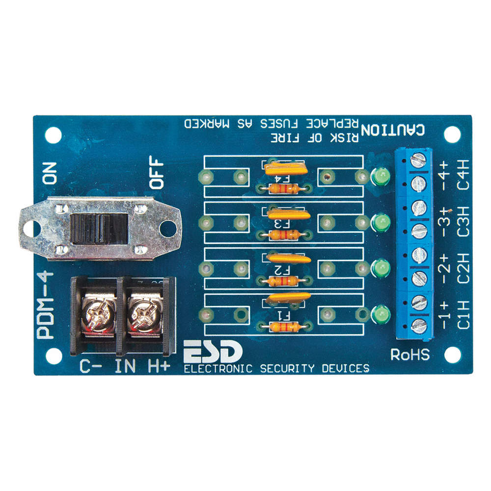
The solution is to individually fuse each leg for the current you expect to be in each leg and appropriately rated the wire for. There are two common methods. A slow-blow fuse is handy as it won’t open under small surges but will under a short before the wire can heat up and melt. Another option is a PTC. It is basically a special resistor that when it heats up, it opens. And will stay open until power is removed and the over current is resolved. These are nice since they auto reset.
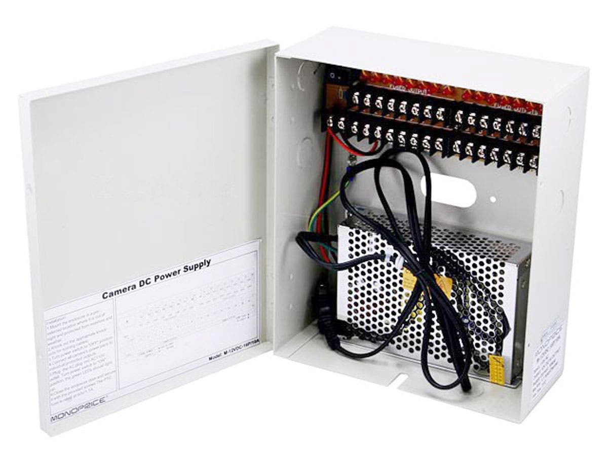
Here is a handy box for DIY escape room builders. https://www.monoprice.com/product?p_id=6875. There are better options for sure like DIN circuit breaker blocks and more specialized PTC power distribution blocks, but this is a reasonable suggestion to reduce fire potential. An alternative: https://www.grainger.com/product/48KT20.
Complications
ESD
We’ve all walked across a rug, touched something metal and received a shock. That is ESD, electrical spark discharge. Besides being annoying to us, it’s deadly to electronics. That walk across the rug or pulling scotch tape off can generate 15,000 Volts, no problem. Most small boards from Spark Fun and Adafruit contain chips which are very sensitive to ESD. Any chip is sensitive to ESD. If you are in a dry environment, you can easily blow up your Arduino boards during development. Worse, if any of the signals are accessible to your customers, they will likely zap your electronics as well.
Two things. One, keep board signals away from your customers so they can’t zap your electronics. Two, protect your circuits with a TVS.
A TVS, short for transient voltage suppressor, is simple a two-legged electrical device which will clamp voltage spikes and protect your circuit board. Here is a sample of one: https://www.digikey.com/product-detail/en/littelfuse-inc/SA5.0A-B/F5310-ND/715761. Wire this between ground and your signal and it will take the hit instead of your microcontroller. More details on this part here: http://www.littelfuse.com/~/media/electronics/datasheets/tvs_diodes/littelfuse_tvs_diode_sa_datasheet.pdf.pdf. These devices have the added benefit here of adding capacitance (about 1000pf) to your signal. More on that below.
Voltage Drop
As covered above, using the correct wire gauge for your circuits, especially your long runs on high current parts, can be detrimental. The classic example is something like a large 12V maglock that draws 1A. You want to have an emergency release for this maglock in the control room by using a disconnect switch. The control room is 50 feet away. If you run 24 AWG, only 9.4V will get to the maglock. It will probably work, but it won’t be as strong. Spend the extra few dollars on the 16 AWG and get 11.6V to your maglock. Also note, that if your maglock was running 24V, you could run 18 AWG.
Loss of voltage in DC electronics is a very real problem which can cause headaches and other problems later. Wires are not perfect. They have small resistances that add up significantly over distance.
Any large room or room with long runs should just run 24V to keep your life simpler.
Back EMF
EMF is short for electromotive force. Big word, but all it means is back current. When an inductor is powered, a EMF passes through it. When it turns off, a back EMF passes through it. You are probably thinking you don’t care about inductors, but all of the maglocks and relays used in escape rooms are inductors. Common problems people describe are erratic behavior, system resets when I turn on or turn off something, or a lockup. If you experience these issues, you likely have a Back EMF problem.
What is happening here is that current is flowing through an inductor, which could be a relay, motor, transformer, or maglock; anything with coils of wires (which form inductors). When these devices are switched, they cause a current spike, which causes a voltage spike, and the combination cause energy to jump out of the wire and into other wires. Or the spike overloads something directly connected. Either way, it’s bad. So, what you have to do is squash the spike.
For simple circuits, a diode or TVS (transient voltage suppression) can be inserted to prevent back EMF.
MOVs (metal oxide varistors) are also an option. You see these inside a quality maglock, but sometimes they are not sufficient especially when you have long cable runs. https://progeny.co.uk/back-emf-suppression/
More info here: https://en.wikipedia.org/wiki/Flyback_diode
Signal Integrity
There are a lot of factors that go into a reliable electronics control system. Keeping your signal clean and accurate takes a bit of work. Input signals like switches can be susceptible to interference because they are high impedance devices. Output devices like your maglocks can cause a lot of interference. So can things like motors and other high current devices. These devices are referred to as ‘inductive’ and create current spikes when they turn on and turn off. We need to take a two-path approach, protect inputs so they are less susceptible to interference and clamp outputs so that they make less interference.
Protecting Inputs
Input circuits to a microcontroller are high impedance. This means it takes very little energy to change the voltage on the wire, and therefore, change a digital input from high to low or low to high. A typical situation is running a switch to an input on an Arduino.
It seems so convenient as the Arduino has built in pull-ups and one just needs to pull the line low with a switch and you’re done! No! There are many things wrong with this. One, the internal pull-up is only 20K on a good day and can be as high as 50K. At 5V, that is 250uA to 100uA respectively. When the switch is closed, there is a solid connection to ground. When the switch is open, the input pin is very susceptible to noise (other electrical signals exerting unwanted energy onto your circuit). It is important that the input pin is driven (loaded/controlled) in both states of the switch.
Here are a few keys to keeping your system working as expected:
- Add capacitance. Adding a small capacitor on your input pins can increase the loading dynamically. Capacitors are resistant to changes in voltage. Therefore, it will take more energy to change the voltage on your input pin.
- Load both sides. In the case of the switch, provide a much smaller pull-up, something to draw about 5mA. For 5V, this is 1K.
- Use a larger voltage swing. As explained above, 5V should only be used for short, in cabinet wiring (controller next to button). So when running control signals longer distances, use a larger voltage swing to increase noise immunity. Think of it like this, if you have a 5V signal and there is 1 volt of noise, then that’s 20% of your signal. If you have a 12V signal and get same 1 volt of noise, that is 8% of your signal. Built in immunity.
- Use a proper input filter for an Arduino pin (or any 3V or 5V digital input) that uses an industrial control voltage.
- Even when the electrical world is cleaned up, electronics still respond much faster than humans can. A very common practice is to write a de-bounce filter in your software. It’s nothing more than making sure an input is there repeatedly over a period of time. Reading an input as active once could be an anomaly, but reading it active 3 times over 30 milliseconds means it probably is really a person hitting that button.
Conclusion
Escape room operators tend to fall into two camps, people who want to build almost everything themselves and those who just want to write checks. Here at Escape Room Techs, we want to enable both – we love building things, and we particularly love helping people build things right. Keeping escape rooms safe is key to the growth of our industry.
Whether you’re a do-it-yourselfer or not, it’s your responsibility to keep the public, your employees and your investment safe from damage, and that requires a comprehensive understanding of the electrical safety issues that are intrinsic to building an immersive entertainment experience. We’re always available to help!